| Drag Meter |
|
You can see the Wing Drag Meter to the right of the variometer. The instrument was manufactured by Replogle and installed by Dick Johnson as part of the system he designed to measure the wing's laminar flow. The theory and application of this idea is detailed in his article in the October 1983 issue of Soaring Magazine. |
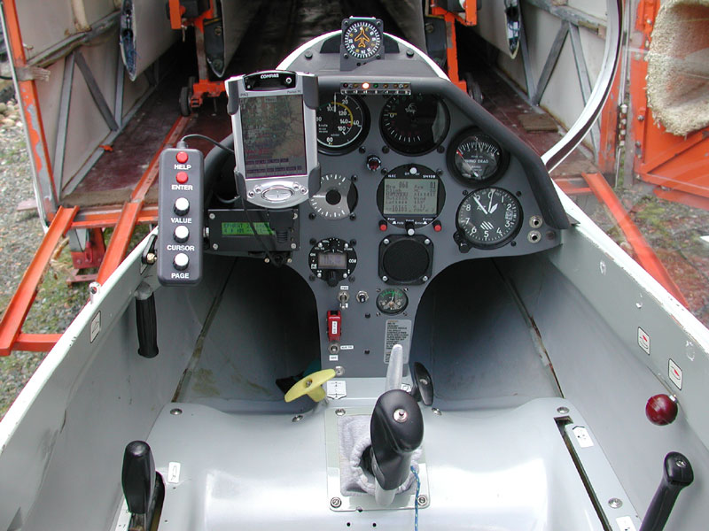 |
Essentially, the meter reads the differential pressure between the pitot air from nose pitot and the summed pressure from a drag rake installed on the left wing. When the airflow over the wing is laminar, the pressures cancel each other out and the drag meter presents a low reading, indicating low drag. If I get the flaps out of position with the airflow over the wing - meaning the wrong flap setting for the current airspeed and vice versa - the meter reads high drag because the drag rake is getting non-laminar, turbulent air and the summed pressure in the rake is lower than the pressure coming from the nose pitot.
In turbulent thermals, the meter pegs out to the right because of the bad airflow over the nose pitot and airflow separation on the wing. The biggest problem with the system is that the drag rake is easily knocked off the wing when removing it from the trailer. Doing this caused me to fabricate a new one, so I pulled out my 1983 copy of Soaring and followed the detailed instructions.
|
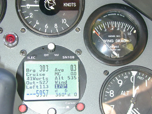 |
First step, get some 4mm thick Lexan and make it rectangular. Dave Piotrowski donated this drill press to the Glider Maintenance Division and I chucked an end mill in it and set about squaring up this chunk of plastic. |
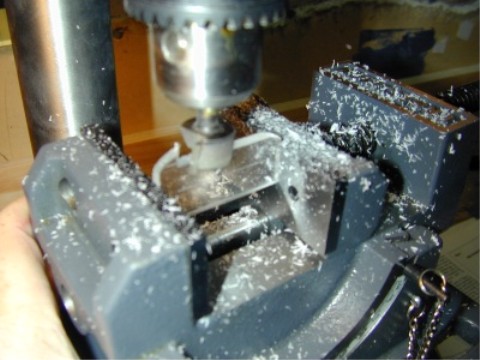 |
Once it's all squared up and milled to size, I marked a centerline for the first drill hole - right down the center of the Lexan. This hole will be the central channel for summing all the pressures. |
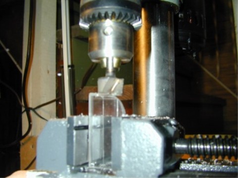 |
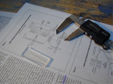
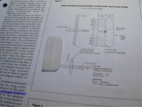
Here's the Lexan with the center hole drilled. That's the 1983 Soaring article it's laying on top of. The illustration in the article is full size, but it's for Dick's Ventus - the Nimbus has a bit larger chord, so I had to do some math to get the proper spacing between rake pitots. |
 |
|
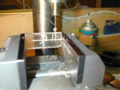
The rake pitots being drilled. |
 |
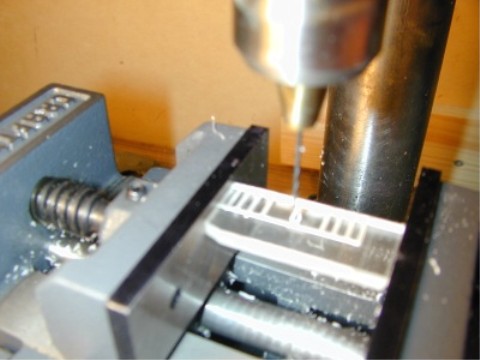
Above - fuzzy picture of all the rake pitots drilled, and now I'm drilling the center hole for the tube I'll insert to take the summed pressure to the small neoprene tubing that runs down the flap, into the wing root and up to the cockpit instrument panel. |
 |
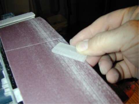
I sand the drag rake to give it an airfoil shape and round the corners. In the process, I reduce the overall thickness of the rake from 4mm to 3mm - per the drawing. |
 |
|
Finished, just needs final polishing and the cutout for the flap trailing edge mounting. |
 |
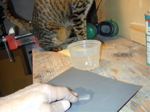
The polishing begins with 600, followed by 1500. The Tabby Cat is up from his nap and comes down to observe the final stages of fabrication |
 |
|
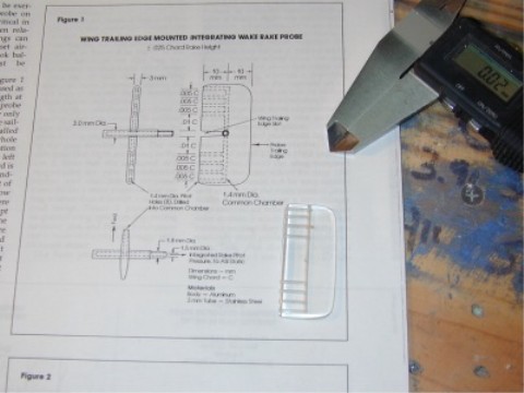
Drag Rake polished and ready for final inspection. |
 |
|
Final inspection always requires a hardness test performed by the Tabby Cat - it appears the Lexan is checking out just fine. |
 |
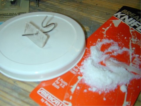
A very small brass tube (1.4mm I.D.) is bent to shape and pressed through the central hole. I mixed up some 5 Minute epoxy and thickened it with colloidal silica for extra strength and glued the tube in place. |
 |
|
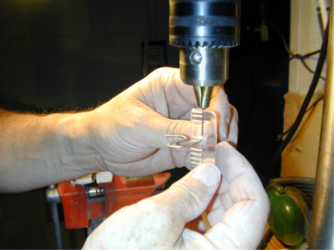
After the epoxy dried, I drilled a hole right through the brass tube to channel air from the pitot manifold to the brass tube. |
 |
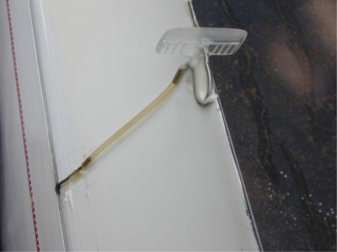
Drag rake epoxied in place on the flap trailing edge. The neoprene tube runs to another, .06 diameter Tygon tube in the flap cove and out to the wing root. You can see the hole in the flap seal where it runs in. |
 |
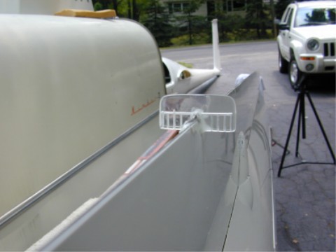
The drag rake installation is complete. You can clearly see the 8 pitots connected by the central manifold. I plugged the lower (left in the photo) end of the central manifold with epoxy so the air going in the 8 pitots must go out the brass tube, down the Tygon line and into the cockpit drag meter. |
 |
Below - January 2006, I decide I will try to make an Althaus drag rake and see how it works on the Nimbus. The Althaus rake is described in this article: http://www.owp.us/Althaus/AlthausDragProbe.asp The Tabby Cat is doing receiving inspection on the stainless tubing I purchased from my favorite glider parts supply vendor: www.Mcmaster.com |
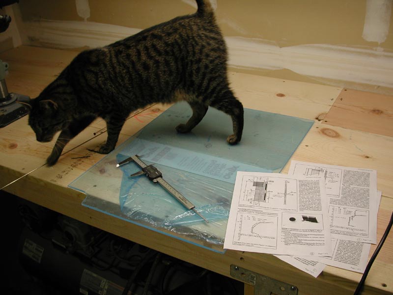 |
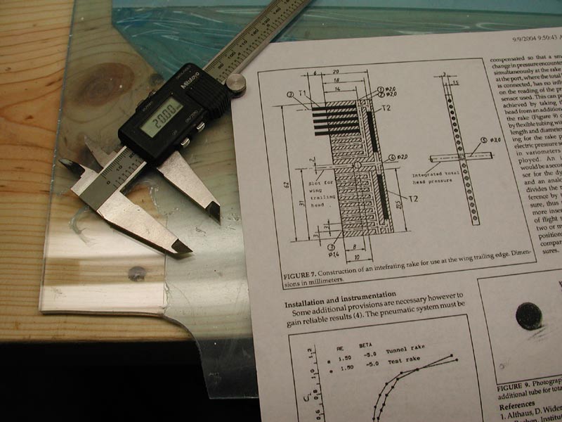
| I cut a piece of 2mm acrylic to the dimensions detailed in the Althaus article. |
 |
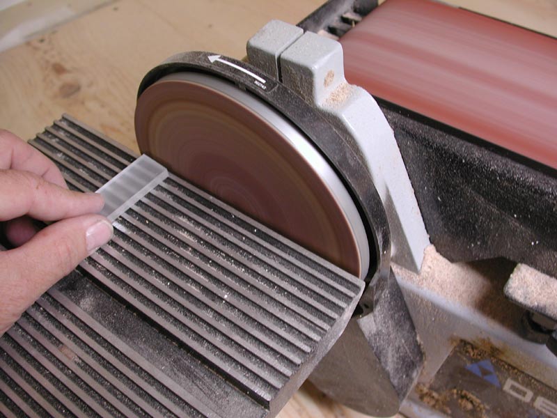
| A bit of finishing.. |
 |
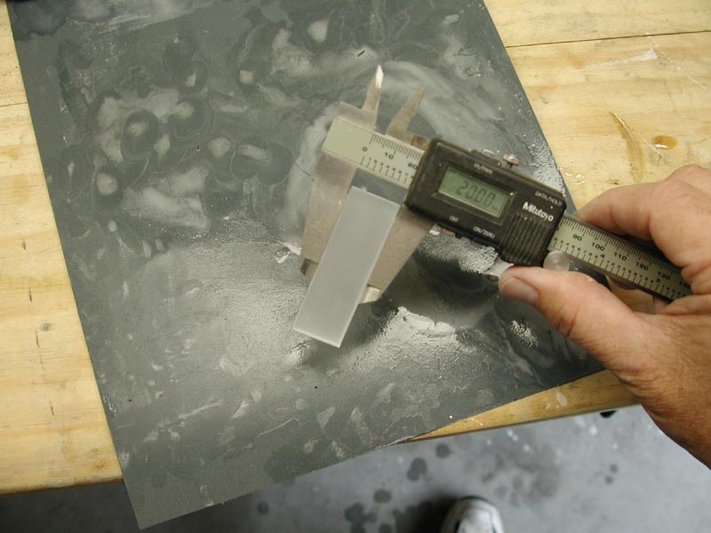
| ...and polishing -to get it to spec. |
 |
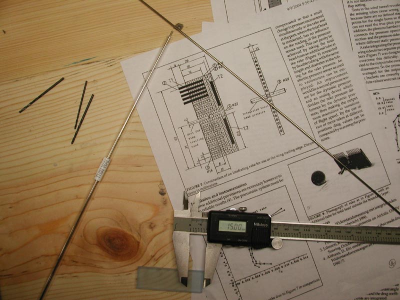
| Next I have to drill the holes for the tubing and assemble the pitot tubes and summing chambers per the drawing. |
 |
|